10/31/2023: Localization News - Dead of the Brain 1!

No, NOT a trick, a Halloween treat! Presenting the Dead of the Brain 1 English patch by David Shadoff for the DEAD last official PC Engine CD game published by NEC before exiting the console biz in 1999! I helped edit/betatest and it's also a game I actually finished in 2023, yaaay! Shubibiman also did a French localization. github.com/dshadoff/DeadoftheBrain
twitter.com/NightWolve/PCENews
Main Menu
Menu

Show posts

This section allows you to view all posts made by this member. Note that you can only see posts made in areas you currently have access to.

Show posts Menu

Messages - grendelrt

#1
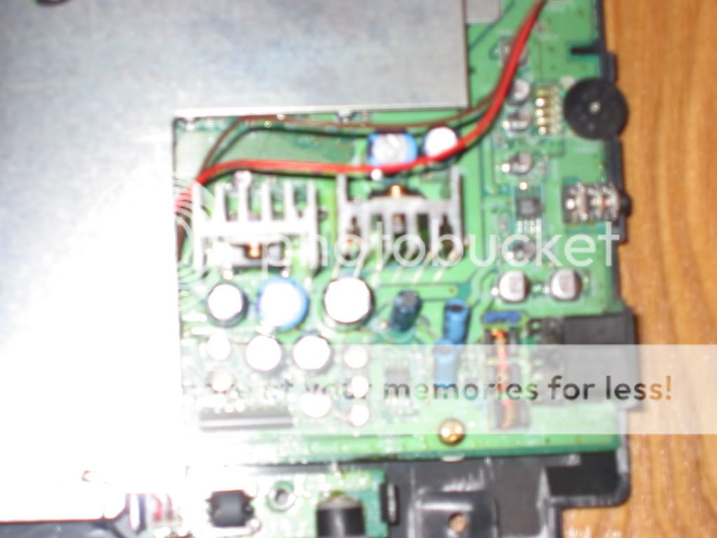
SUCCESS! The via near the IC521 was bad! Wooo, finally ahha. Voltages at 521 went back to normal with a quick patch wire to ground.
IMG

Sound is good, and since the recap I think my video quality went up a little bit. Another duo is still alive, hanks for all the help! =)
#2
I resoldered the caps near IC107  ( thanks Keith!) and the voltage did drop a tiny bit, it went from
IC 107 Beside cd rom area
1- 9.36
7- 9.9
8- 9.9

to

IC 107 Beside cd rom area
1- 9.5
5 - 5
6 - 5
7- 7.5
8- 10

I tried tracing the path from the legs on the bottom of the board, i moved that chip that was blocking but didnt want to pull it up too much. I lost the traces though.
Pin 6 on IC 107 4558 - Bottom of board R134 to R140, then I couldnt find where it went next. '
Pin 7 on IC 107 4558 - Bottom of board R145 to R144 to solder joint that splits to R142 and R143.

Took some pics if it helps
IMG
IMG

This one looks really cool too ha!
IMG
#3
OK may have found something else, not sure if its an issue or not. I hooked my probe to the main ground strap that attached to the cd rom board and started testing the ground legs on the caps in that area. The five caps below (one you cant see its small behind the left cluster) I dont get continuity from the ground strap on the left leg. I took a small piece of wire and connected one leg to another that was getting continuity, then that leg started getting continuity. Weird thing is when I run the machine and use the left leg as negative and the right as positive I still get a good volatage reading of 3.8v. So I am guessing there are maybe two seperate ground planes?
IMG
#4
Thanks for the help =) Of those caps you circled , the bottom 22uf cap was really bad underneath when I removed it yesterday. I removed some pcb at the hole attached to that solder pad and soldered the leg of the cap to that and then ran a line from the ground leg of the cap behind it to ground it. I was getting plenty of voltage through this cap last night when I tested, but maybe I didnt repair this area correctly.

Repair
IMG

Original Damage
IMG

I flipped the board and did find this one area with a black mark on a trace, I tested continuity between the jumper and leg around it and got continuity.
IMG
#5
My main computer:

Athlon64 X2 4400+ @ 2.4GHZ
2GB GSkill DDr500
2x eVGA 7800GTX 512 in SLI
X-FI Fatality
NEC 3520 DVDRW DL 16X
Seasonic S12 600W
Antec P180
Seagate 300GB SATA2
WD 80GB SATA
21 Inch Gateway 16:9 LCD

Pic before wire cleanup, no SLI bridge installed yet

IMG

My MAME Machine:
AthlonXP 3000+
1GB DDR400
WD 80GB SATA
Soundstorm 5.1 DD Live
Radeon 9800 Pro
NEC 3520 DVDRW 16X DL
46 Inch Samsung DLP
Hotrod Joystick

1 Laptop and like 6 other parts computers hehe.
#6
I finished my region mod tonight, works great so far. I figured I would post some things I learned that are not in the standard faqs floating around.

1. Get some 30gauge wire. This made my life so much easier using this wire (first time I wired it with solid core wire that wasnt flexible, didnt work either lol). I got mine here:

Wire Link

2. You can get the switch here:
8PDT - Push On / Push Off Maintained Contacts

3. Here is how to wire the switch:

IMG

4. I used a 15W radio shack soldering iron.

My final results, I didnt put the shield back on, not sure about that one.

IMG
#7
just found this pic on DLITE's site. I see where he puts the crossovers. Now I am trying to figure out where the pins  starting at 23 go. Any help would be much appreciated :)

IMG
https://i63.photobucket.com/albums/h152/grendelrt/DuoRX3.jpg
#8
I just got in my switch for the region mod. I understand how the pinouts on the mod work,

pins: 23 -> 15
      22 -> 16
      21 -> 17
      20 -> 19
      --------
      19 -> 20
      17 -> 21
      16 -> 22
      15 -> 23

but I don't get how to wire it to the switch. It has two sides of two rows of contacts. I think you only use one side, they are just different contact types. Could someone help me out with this please =)

It looks like this on one side pretty much

n n n n n n n n n n n n

n n n n n n n n n n n n

IMG
https://i63.photobucket.com/albums/h152/grendelrt/pic.jpg
#9
Well the only thing i could find at the local radio shack was a 10uf 35v. DO you think this is enough ? The capacitors on the board are labeled 10 16. So I am guessing 10uf 16v. D Lite said 50V for his replacement, but I am not sure of anywhere else to find a capacitor locally. By the way, this things are soooo much tinier than they look in the pics lol

Well I finished, I used the 35v caps and they seem to be working fine. I had no fade in music with Lords of Thunder, which almost always happened. I tried to take pictures along the way to help others, but they didn't come out, the only one that is half decent was the final product pic:

IMG

Oh and here is a video for your enjoyment and my moment of happiness =)

s63.photobucket.com/albums/h152/grendelrt/?action=view¤t=pic017avi.flv